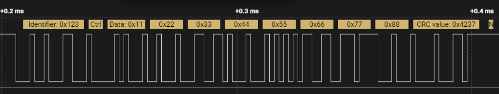
WLED

I heard a lot about “if you want to control LEDs, use WLED“. I never had a need to control LEDs (the strip type), but today I had some spare time and I tested it with a spare ESP8266 and a single WS2812B LED. WLED is not really made for single LEDs, but as a proof-of-concept it’ll have to do.

Can’t say much here though: the install went as expected, connecting to the access point it created was straightforward, setting up my WiFi credentials worked, and controlling the single LED via web interface or Android app was as easy as it can get. This was one of the easiest installs of any IoT thing I ever had.

Now I do have to get me some LED strips to play a bit more with it…

Update: Ok, got myself a 60 LED WS2812B strip. And WLED effects look much better for obvious reasons. And you can split the 60 LEDs into segments and set their respective colors via curl easily:

❯ curl -s -X POST http://192.168.21.138/json -H "Content-Type: application/json" -d '{seg:[{},{},{col:[[0,0,100]]}]}' | jq .
{
  "success": true
}

Above sets the color of the 3rd segment to blue (assuming the effect is “Solid”). That’s way better and easier than any other API I’ve seen for WiFi connected lights.

Advertisement

Control USB Hub Power

Today via reddit I found a neat little utility I never heard of: uhubctl. It can turn off/on/toggle power on USB ports. And it works perfectly on my old 7 port USB 3 hub (look for the 1050:0120 Yubikey on hub 2-4.1 port 1):

❯ uhubctl
Current status for hub 3-4.1 [2109:0812 VIA Labs, Inc. USB3.0 Hub, USB 3.00, 4 ports, ppps]
  Port 1: 02a0 power 5gbps Rx.Detect
  Port 2: 02a0 power 5gbps Rx.Detect
  Port 3: 02a0 power 5gbps Rx.Detect
  Port 4: 02a0 power 5gbps Rx.Detect
Current status for hub 3-4 [2109:0812 VIA Labs, Inc. USB3.0 Hub, USB 3.00, 4 ports, ppps]
  Port 1: 0263 power 5gbps U3 enable connect [2109:0812 VIA Labs, Inc. USB3.0 Hub, USB 3.00, 4 ports, ppps]
  Port 2: 02a0 power 5gbps Rx.Detect
  Port 3: 02a0 power 5gbps Rx.Detect
  Port 4: 02a0 power 5gbps Rx.Detect
Current status for hub 2-4.1 [2109:2812 VIA Labs, Inc. USB2.0 Hub, USB 2.10, 4 ports, ppps]
  Port 1: 0103 power enable connect [1050:0120 Yubico Security Key by Yubico]
  Port 2: 0100 power
  Port 3: 0100 power
  Port 4: 0100 power
Current status for hub 2-4 [2109:2812 VIA Labs, Inc. USB2.0 Hub, USB 2.10, 4 ports, ppps]
  Port 1: 0503 power highspeed enable connect [2109:2812 VIA Labs, Inc. USB2.0 Hub, USB 2.10, 4 ports, ppps]
  Port 2: 0100 power
  Port 3: 0100 power
  Port 4: 0103 power enable connect [1852:7022 FiiO DigiHug USB Audio]

❯ uhubctl -a off -l 2-4.1 -p 1
Current status for hub 3-4.1 [2109:0812 VIA Labs, Inc. USB3.0 Hub, USB 3.00, 4 ports, ppps]
  Port 1: 02a0 power 5gbps Rx.Detect
Sent power off request
New status for hub 3-4.1 [2109:0812 VIA Labs, Inc. USB3.0 Hub, USB 3.00, 4 ports, ppps]
  Port 1: 0080 off
Current status for hub 2-4.1 [2109:2812 VIA Labs, Inc. USB2.0 Hub, USB 2.10, 4 ports, ppps]
  Port 1: 0103 power enable connect [1050:0120 Yubico Security Key by Yubico]
Sent power off request
New status for hub 2-4.1 [2109:2812 VIA Labs, Inc. USB2.0 Hub, USB 2.10, 4 ports, ppps]
  Port 1: 0000 off

❯ uhubctl
Current status for hub 3-4.1 [2109:0812 VIA Labs, Inc. USB3.0 Hub, USB 3.00, 4 ports, ppps]
  Port 1: 0080 off
  Port 2: 02a0 power 5gbps Rx.Detect
  Port 3: 02a0 power 5gbps Rx.Detect
  Port 4: 02a0 power 5gbps Rx.Detect
Current status for hub 3-4 [2109:0812 VIA Labs, Inc. USB3.0 Hub, USB 3.00, 4 ports, ppps]
  Port 1: 0263 power 5gbps U3 enable connect [2109:0812 VIA Labs, Inc. USB3.0 Hub, USB 3.00, 4 ports, ppps]
  Port 2: 02a0 power 5gbps Rx.Detect
  Port 3: 02a0 power 5gbps Rx.Detect
  Port 4: 02a0 power 5gbps Rx.Detect
Current status for hub 2-4.1 [2109:2812 VIA Labs, Inc. USB2.0 Hub, USB 2.10, 4 ports, ppps]
  Port 1: 0000 off
  Port 2: 0100 power
  Port 3: 0100 power
  Port 4: 0100 power
Current status for hub 2-4 [2109:2812 VIA Labs, Inc. USB2.0 Hub, USB 2.10, 4 ports, ppps]
  Port 1: 0503 power highspeed enable connect [2109:2812 VIA Labs, Inc. USB2.0 Hub, USB 2.10, 4 ports, ppps]
  Port 2: 0100 power
  Port 3: 0100 power
  Port 4: 0103 power enable connect [1852:7022 FiiO DigiHug USB Audio]

❯ uhubctl -a on -l 2-4.1 -p 1
Current status for hub 3-4.1 [2109:0812 VIA Labs, Inc. USB3.0 Hub, USB 3.00, 4 ports, ppps]
  Port 1: 0080 off
Sent power on request
New status for hub 3-4.1 [2109:0812 VIA Labs, Inc. USB3.0 Hub, USB 3.00, 4 ports, ppps]
  Port 1: 02a0 power 5gbps Rx.Detect
Current status for hub 2-4.1 [2109:2812 VIA Labs, Inc. USB2.0 Hub, USB 2.10, 4 ports, ppps]
  Port 1: 0000 off
Sent power on request
New status for hub 2-4.1 [2109:2812 VIA Labs, Inc. USB2.0 Hub, USB 2.10, 4 ports, ppps]
  Port 1: 0101 power connect [1050:0120]

❯ uhubctl
Current status for hub 3-4.1 [2109:0812 VIA Labs, Inc. USB3.0 Hub, USB 3.00, 4 ports, ppps]
  Port 1: 02a0 power 5gbps Rx.Detect
  Port 2: 02a0 power 5gbps Rx.Detect
  Port 3: 02a0 power 5gbps Rx.Detect
  Port 4: 02a0 power 5gbps Rx.Detect
Current status for hub 3-4 [2109:0812 VIA Labs, Inc. USB3.0 Hub, USB 3.00, 4 ports, ppps]
  Port 1: 0263 power 5gbps U3 enable connect [2109:0812 VIA Labs, Inc. USB3.0 Hub, USB 3.00, 4 ports, ppps]
  Port 2: 02a0 power 5gbps Rx.Detect
  Port 3: 02a0 power 5gbps Rx.Detect
  Port 4: 02a0 power 5gbps Rx.Detect
Current status for hub 2-4.1 [2109:2812 VIA Labs, Inc. USB2.0 Hub, USB 2.10, 4 ports, ppps]
  Port 1: 0103 power enable connect [1050:0120 Yubico Security Key by Yubico]
  Port 2: 0100 power
  Port 3: 0100 power
  Port 4: 0100 power
Current status for hub 2-4 [2109:2812 VIA Labs, Inc. USB2.0 Hub, USB 2.10, 4 ports, ppps]
  Port 1: 0503 power highspeed enable connect [2109:2812 VIA Labs, Inc. USB2.0 Hub, USB 2.10, 4 ports, ppps]
  Port 2: 0100 power
  Port 3: 0100 power
  Port 4: 0103 power enable connect [1852:7022 FiiO DigiHug USB Audio]

Neat as now I can power control all kind of USB devices and there’s plenty of stuff which uses USB as power source.

Moving Two Things

Learning G-Code is quite interesting: it’s really old, really simple, and yet surprisingly complex if you want to get CNC cuts 100% perfect. Luckily my use-cases are much simpler, but I still would like to move 2 axis concurrently: e.g. move along the x-axis from 0 to 400mm, and rotate the a axis from 0 to 180 degrees so that they start and end together.

Adding a Servo

Step 1 is to connect a servo, which was not as easy as I thought since there’s no dedicated servo connector I can readily use on the DLC32. Luckily there are plenty pins to get GND, 5V and a PWM signal. This is the section I added to the config.yaml:

  a:
    steps_per_mm: 10
    max_rate_mm_per_min: 100000.0
    acceleration_mm_per_sec2: 100000.0
    max_travel_mm: 180.0
    soft_limits: true
    homing:
      cycle: 0
      mpos_mm: 0
      positive_direction: false
    motor0:
      rc_servo:
        pwm_hz: 50
        output_pin: gpio.25
        min_pulse_us: 1000
        max_pulse_us: 2000

IO25 is readily available on the EXP1 connector, so I used 5V, GND and IO25 from EXP1:

EXP1 and EXP2 (unused with FluidNC)

Now I can use G-Code like this:

  • G0A90 to move the servo to the neutral position 90° (assuming 1ms=0°, 2ms=180°). The actual movement depends on the servo. Most move only 90° in total.
  • G1X300A10F200 now does:
    • Move to x=300mm and rotate a to 10° at a feed-rate of 200 mm/minute. If x=100 at the start, this movement will take 1 minute.
    • During the movement, a ?<ENTER> will show the current positions:
?
<Run|MPos:221.533,0.000,0.000,126.500|FS:200,0|Pn:PYZ>
ok
[...about 30 seconds later...]
?
<Idle|MPos:300.000,0.000,0.000,10.000|FS:0,0|Pn:PYZ>
ok

Moving Things

Servos are great to rotate/move things around, but they are limited in their capabilities. Steppers are more versatile and controlling them is not hard with the help of stepper driver modules. But since they do expect a fairly high rate of step pulses, a dedicated controller is needed. This is a solved problem though: GRBL takes care of that and it accepts G-Code which looks like this:

G0X100

To move the X axis to the position at 100mm. Generating movements are simply a stream of such strings. Sending a

G0X100.5

after 1 second will results in a moving speed of 0.5mm/s. A nice part of GRBL is that it also controls acceleration and deceleration. Important for moving heavy objects for long distances at high speed.

But traditional GRBL uses an Arduino which is not network connected. Luckily GRBL was ported to the ESP32 CPU with its WiFi interface. Even better: FluidNC was created improving on a lot of areas, like configuration (no need to recompile for a config change) and connectivity (IP or Bluetooth and of course serial).

Naturally that looked like an interesting thing to try out.

Hardware

  • A NEMA17 stepper (200 steps/rotation) with a timing belt moving a slider along an aluminium profile
  • A stepper driver (DRV8825 I think I use)
  • Makerbase MKS DLC32
  • A end-stop sensor (microswitch in my case)

Configuration

  • Get the FluidNC firmware from here
  • Erase the FLASH on the ESP32 with the included erase script (on Windows: run erase.bat)
  • Flash the WiFi version (on Windows: run install-wifi.bat)
  • You should now be able to connect via fluidterm.bat and for any debugging this is very helpful as you can see the boot process and early errors.
  • Configure WiFi according to this. That should be it as most default are sensible and thus not much to configure beside the SSID and the password:
$Sta/SSID=myssid
$Sta/Password=mypasswordforthessid
  • Reboot ($Bye) and check network parameters ($I):
$I
[VER:3.4 FluidNC v3.4.3:]
[OPT:PHS]
[MSG: Machine: Slider]
[MSG: Mode=STA:SSID=myssid:Status=Connected:IP=192.168.3.18:MAC=66-55-44-33-22-11]
ok
  • Connect to the Web UI at http://192.168.3.18 (the IP you get via $I obviously)
  • Upload a file for the configuration for the MKS DLC32 and the hardware setup you have. In my case: I only use the x-axis, so my config file looks like below. It’s almost 100% of the example config and the main changes are:
    • idle_ms=255 which keeps the stepper powered forever so it can hold things in place
    • steps_per_mm and max)travel_mm for the x-axis to match my hardware
    • turn off homing for y and z axis since I don’t use them
board: MKS-DLC32 V2.1
name: Slider
meta: (01.01.2022) by Skorpi

kinematics:
  Cartesian:

stepping:
  engine: I2S_STREAM
  idle_ms: 255
  pulse_us: 4
  dir_delay_us: 1
  disable_delay_us: 0
axes:
  shared_stepper_disable_pin: I2SO.0
  x:
    steps_per_mm: 40.7
    max_rate_mm_per_min: 15000.000
    acceleration_mm_per_sec2: 500.000
    max_travel_mm: 440.000
    soft_limits: true
    homing:
      cycle: 1
      positive_direction: false
      mpos_mm: 0.000
      feed_mm_per_min: 300.000
      seek_mm_per_min: 5000.000
      settle_ms: 500
      seek_scaler: 1.100
      feed_scaler: 1.100

    motor0:
      limit_neg_pin: gpio.36
      hard_limits: true
      pulloff_mm: 2.000
      stepstick:
        step_pin: I2SO.1
        direction_pin: I2SO.2

  y:
    steps_per_mm: 428.0
    max_rate_mm_per_min: 12000.000
    acceleration_mm_per_sec2: 300.000
    max_travel_mm: 440.000
    soft_limits: true
    homing:
      cycle: 0
      positive_direction: false
      mpos_mm: 0.000
      feed_mm_per_min: 300.000
      seek_mm_per_min: 5000.000
      settle_ms: 500
      seek_scaler: 1.100
      feed_scaler: 1.100

    motor0:
      limit_neg_pin: gpio.35
      hard_limits: false
      pulloff_mm: 2.000
      stepstick:
        step_pin: I2SO.5
        direction_pin: I2SO.6:low

  z:
    steps_per_mm: 157.750
    max_rate_mm_per_min: 12000.000
    acceleration_mm_per_sec2: 500.000
    max_travel_mm: 80.000
    soft_limits: true
    homing:
      cycle: 0
      positive_direction: false
      mpos_mm: 0.000
      feed_mm_per_min: 300.000
      seek_mm_per_min: 1000.000
      settle_ms: 500
      seek_scaler: 1.100
      feed_scaler: 1.100

    motor0:
      limit_neg_pin: gpio.34
      hard_limits: false
      pulloff_mm: 1.000
      stepstick:
        step_pin: I2SO.3
        direction_pin: I2SO.4

i2so:
  bck_pin: gpio.16
  data_pin: gpio.21
  ws_pin: gpio.17

spi:
  miso_pin: gpio.12
  mosi_pin: gpio.13
  sck_pin: gpio.14

sdcard:
  cs_pin: gpio.15
  card_detect_pin: NO_PIN

control:
  safety_door_pin: NO_PIN
  reset_pin: NO_PIN
  feed_hold_pin: NO_PIN
  cycle_start_pin: NO_PIN
  macro0_pin: gpio.33:low:pu
  macro1_pin: NO_PIN
  macro2_pin: NO_PIN
  macro3_pin: NO_PIN

macros:
  startup_line0:
  startup_line1:
  macro0: $SD/Run=lasertest.gcode
  macro1: $SD/Run=home.gcode
  macro2:
  macro3:

coolant:
  flood_pin: NO_PIN
  mist_pin: NO_PIN
  delay_ms: 0

probe:
  pin: gpio.22
  check_mode_start: true

Laser:
  pwm_hz: 5000
  #L on Beeper / IN on TTL
  output_pin: gpio.32
  enable_pin: I2SO.7
  disable_with_s0: false
  s0_with_disable: false
  tool_num: 0
  speed_map: 0=0.000% 0=12.500% 1700=100.000%
# 135=0mA 270=5mA 400=10mA 700=16mA
user_outputs:
  analog0_pin: NO_PIN
  analog1_pin: NO_PIN
  analog2_pin: NO_PIN
  analog3_pin: NO_PIN
  analog0_hz: 5000
  analog1_hz: 5000
  analog2_hz: 5000
  analog3_hz: 5000
  digital0_pin: NO_PIN
  digital1_pin: NO_PIN
  digital2_pin: NO_PIN
  digital3_pin: NO_PIN

start:
  must_home: false

  • When done, name the file you just uploaded:
$Config/Filename=config2.yaml

  • Then you have to “Home” once so the controller knows where everything is (using telnet for a change since network is up now):
❯ telnet 192.168.3.18 23
Trying 192.168.3.18...
Connected to 192.168.3.18.
Escape character is '^]'.

Grbl 3.4 [FluidNC v3.4.3 (wifi) '$' for help]
$H
ok
?
<Idle|MPos:0.000,0.000,0.000|FS:0,0|Pn:PYZ|Ov:100,100,100>
ok
  • and now you should be able to move the slider via very simple G-Code (x axis to 100mm position):
G0X100
ok
  • If you get an error for the $H command, it’s likely that you don’t have a working end-stop for the axis which are supposed to have one. A quick fix is to use $X to disable end-stop checks. It’ll allow axis movements, but it does no checks for movements.

Node.js sending commands

GRBL has no single command to do a slow controlled motion, so in order to do that, a program needs to send G-Code commands to it. Node.js to the rescue! Below test program moves the slider 2 times back and forth and when done, it closes the connection:

// Test to send commands to GRBL (FluidNC)

const net=require('net');

let stateIsIdle=false;
let statusLine='';

function gotALine(s) {
  console.log('Got a line: '+s);
  if (s.startsWith('<Idle|')) {
    if (stateIsIdle==true) {
      console.log('Idle detected again');
      client.end();
      process.exit(0);
    } else {
      stateIsIdle=true;
      console.log('Idle detected');
    }
  }
}

let client=new net.Socket();
client.connect(23, '192.168.21.118', () => { console.log('Got connected'); });
client.on('data', (data) => {
  let s=data.toString();
  if (s.indexOf('\n') < 0) {
    statusLine+=s;
  } else {
    statusLine+=s;
    gotALine(statusLine.trim());
    statusLine='';
  }
});

client.on('close', () => { console.log('Closed connection'); });

function sendStatusRequest() {
  if (client) client.write('?\n');
}

setInterval(sendStatusRequest, 1000);

for (let i=0; i<2; ++i) {
  client.write('G0X0\n');
  client.write('G0X400\n');
}

Problems

  • When requesting a status via ‘?’, it seems the stepper steps take a short break which causes a jerky movement. This is very reproducible. Issue created for this. Using I2S_STREAM helps a lot, but it’s not 100% fixed. I2S_STREAM has another problem though…
  • I2S_STREAM seems to be inaccurate: moving 4 times 100mm and then moving back to 0 leaves several mm missing. The same test with I2S_STATIC shows zero error.

Winter project: Colorlight 5A 75B Protocol

I wish the protocol would be officially documented for the Colorlight 5A 75 as it’s an awesome piece of affordable technology to drive those LED panels (see here as an example). I rather like using Ethernet instead of some odd adapter card which is tied to a specific hardware (RPi in above case). Ethernet on the other hand is perfect: it’s fast (Gigabit can transfer a 256×256 24 bit/pixel frame in 1.6µs or over 600fps, cables can be 100m long, you can use (L2) switches to distribute the traffic and you can create traffic with any software which can send Ethernet frames.

To configure the Colorlight 5A 75B, you need software named LEDVISION. It’s needed to configure the panels, their wiring and some other items. Once done, it’s no longer required.

A limitation I did not expect is that LEDVISION does require a Ethernet port to work. It might be possible to send actual frames via WiFi as long as the receiver card is connected to a bridged Gigabit Ethernet port, but that remains to be seen1.

Some frame decoding is visible in the source code of FPP which took the work from the original reverse engineering here. So here the frames I found (Colorlight 5A 75B, version 5A 10.16).

Image Data Frame

Default from LEDVISION software is using 20Hz. I can do about 60Hz but anything higher results in not-so-smooth animations (AKA skipped frames).

  • Display Frame: Show the stored Image
  • eth.type == 0x0107
  • src.mac: 22:22:33:44:55:66 (take this literal)
  • dest.mac: 11:22:33:44:55:66 (this too)
  • Date length: 98
  • Date[21]: Brightness (linear 0..255)
  • 0x00: 0% brightness, 0x03: 1%, 0x05: 2%, 0x08: 3%, 0x0a: 4%, 0x0d: 5%, 0x0f: 6%, 0x1a: 10%, 0x40: 25% brightness, 0x80: 50% brightness, 0xbf: 75% brightness, 0xff: 100% brightness
  • Data[22]: 5 (no idea what this is, but it’s always 5)
  • Date[24,25,26]: Brightness (linear) for R, G and B (to adjust color temperature):
  • 2000K at 10% brightness: 0x1a, 0x0c, 0x01, 6500K at 10% brightness: 0x1a, 0x1a, 0x1a, 2000K at 100% brightness: 0xff, 0x76, 0x06, 4500K at 100% brightness: 0xff, 0xdc, 0x8f, 6500K at 100% brightness: 0xff, 0xff, 0xff, 8000K at 100% brightness: 0xce, 0xd8, 0xff
0000 11 22 33 44 55 66 22 22  33 44 55 66 01 07 00 00
0010 00 00 00 00 00 00 00 00  00 00 00 00 00 00 00 00
0020 00 00 00 bf 05 00 bf bf  bf 00 00 00 00 00 00 00
0030 00 00 00 00 00 00 00 00  00 00 00 00 00 00 00 00
0040 00 00 00 00 00 00 00 00  00 00 00 00 00 00 00 00
0050 00 00 00 00 00 00 00 00  00 00 00 00 00 00 00 00
0060 00 00 00 00 00 00 00 00  00 00 00 00 00 00 00 00
  • Set Brightness Frame: Set frame brightness and color temperature
  • eth.type==0x0aXX (XX=00…ff)
  • Data length: 63 byte
  • Data: XXXXff00…00
  • XX is the brightness from 0x00 (black) to 0xff (100% brightness)
  • 1%=0x28, 2%=0x35, 5%=0x4d, 25%=0x92 , 50%=0xc1, 75%=0xe3, 100%=0xff (based on LEDVISION software)
  • Pixel Data Frame: Send a row of pixels
  • eth.type==0x5500 or 0x5501 (decode from FPP source)
  • Data length: 391 byte (row length * 3 + 7), Pixel format: BGR (for my panel)
  • Ether Type: 0x5500 + MSB of Row Number, or 0x5501 for row 256..511
  • Data[0]: Row Number LSB
  • Data[1]: MSB of pixel offset for this packet
  • Data[2]: LSB of pixel offset for this packet
  • Data[3]: MSB of pixel count in packet
  • Data[4]: LSB of pixel count in packet
  • Data[5]: 0x08 – ?? unsure what this is
  • Data[6]: 0x80 – ?? unsure what this is (I got 0x88)
  • Data[7-end]: RGB order pixel data (resp. BGR for me)

Receiver Card Detection

This is always 3 frames: one to the receiver card, one response from the card (broadcasted), and an ack to the card with Data[2]=1.

  • Detect Receiver Card Frame: eth.type==0x0700
  • Data length: 270 byte
  • Data: 00000000…00
  • Detect Receiver Response Frame: eth.type==0x0805
  • src.mac: 11:22:33:44:55:66
  • dest.mac: ff:ff:ff:ff:ff:ff
  • Data length: 1056 byte
  • Data[0]: Receiver card version (5A)
  • Data[1]: Receiver card version major (10)
  • Data[2]: Receiver card version minor (16)
  • Data[20]: Pixel columns HSB
  • Data[21]: Pixel columns LSB
  • Data[22]: Pixel rows HSB
  • Data[23]: Pixel rows LSB
  • Data[39,40]: 16 bit (at least) counter: frames received / panels (or divide by 4)
  • Data[45, 46, 47, 48]: Run Time in ms: 32 bit (at least) counter
0000   ff ff ff ff ff ff 11 22  33 44 55 66 08 05 04 0a
0010   10 00 00 00 00 00 00 00  00 00 00 00 00 00 00 00
0020   00 00 00 80 00 40 00 00  00 00 00 00 01 02 03 ff
0030   ff ff ff 00 00 0c a8 00  00 00 00 00 08 05 a0 00
0040   00 00 00 00 00 00 00 00  00 00 00 00 ba 00 00 00
0050   00 00 00 00 00 00 00 00  00 00 00 00 00 00 00 00
0060   00 00 00 00 00 00 00 00  00 00 00 00 0f 04 08 00
0070   00 00 00 00 00 00 00 00  00 00 00 00 00 00 01 00
0080   01 00 01 00 00 28 00 ff  ff ff 00 00 00 00 00 00
0090   00 00 0c 03 00 00 00 00  00 00 00 00 00 00 00 00
00a0   00 00 00 00 00 00 00 00  01 00 00 00 00 00 04 00
00b0   00 00 00 00 00 00 00 00  00 00 00 00 00 00 00 00
[...]
0410   00 00 00 00 00 00 00 00  00 00 00 00 00 00 00 00
0420   00 00 00 00 00 00 00 00  00 00 00 00 00 00

Lacking official documentation this is all only a guess. If I had more samples with more versions of the card, it would make those guesses better, but they’d be still guesses.

  • Detect Receiver Response Ack Frame: eth.type==0x700
  • Data length: 270 byte
  • Data: 00000100…00

Why all this trouble?

Now I can find the receiver card (response on 0x0700 packet) and I get the configured pixel size. One thing less the user needs to provide or which has to be hard-coded.

Here the result (source code is here):

Dart sending frames to a Colorlight 5A

Updates

1 When sending frames via WiFi, the result is having…problems. Think of analog TV having a bad reception: you can see what’s going on, but frames are missing, colors are off for a frame, and the first line of the graphics is not always on the first line.

Update 2022-09-29

Somehow I used the wrong offset for the brightness data. Updated now in the code and in this article. Thanks to esbenvb!

Update 2023-02-12

Since I am using TypeScript with Deno a lot recently and Deno has an FFI which is similar to Dart, I thought about porting it to Deno. And it works! Code is here. Tested on x86_64 and on aarch64.

Genki Covert Dock as a Notebook Docking Station

A while ago I bought a Genki Covert Dock for my Switch so I can play on a TV in another room without having to carry the original Switch dock around. The Covert Dock has 3 ports: a USB-C connector for the Switch, HDMI for a TV/monitor and one extra USB3 USB-A connector for typically an Ethernet adapter. It also works as a 30W PD power supply. Everything works well with the Switch. Since the drivers built into the Switch are not many and generally it’s picky about its docking station, often other 3rd party docking stations won’t work. Same applies to the Ethernet adapter which must use the AX88179 chip since that’s what the original Nintendo Ethernet adapter uses.

I got a new notebook recently with Thunderbolt 4 and since it has very few USB ports (2xC, 1xA) and I like to use my USB keyboard, a wireless mouse and Ethernet and an external second monitor, the normal solution is a docking station like this or that. Some supply power, some depend on an existing USB-C PD power supply. Some have multiple video outputs, some USB-A connectors, some have Ethernet, card readers etc.

All I need is: PD pass-though since I got enough USB-PD PSUs, one HDMI port, Gigabit Ethernet, 2 USB-A.

And then it hit me: Those docking stations do basically exactly what the Covert Dock does! Might it work on my notebook too?

And I’m glad to say that it does. It can deliver 30W which is enough to keep a (or my) notebook running without depleting the battery, HDMI works, the USB Ethernet adapter works too.

No need for another docking station! I still need one more USB-A port for keyboard and mouse, but I got a simple USB3 hub which does that just fine.

More LEDs!

6 years ago I built a 10×10 LED matrix using LED strips. While it worked, it would not be possible to build something significantly larger due to financial constraints: a 16×16 matrix costs about US$20 and is about 1cm/pixel. If you want to go big, the current way is via LED matrix panels. Like these.

Driving them is much more complex though: the WS2812B you send a bitstream once and you are done. The LED matrix panels needs a refresh not unlike CRTs do. Given the pixel count, this is perfect work for an FPGA. Which is why boards like the Colorlight 5A 75B do exactly that. It received its pixel stream via Ethernet usually from a video processor like this C2 or that X4. But since it’s using Ethernet, you can also use the Falcon Player since it supports the Colorlight card as an output. And the Ethernet frame format is conveniently described there too.

So what’s the point? Do I need a LED wall? Of course I don’t need one, but:

  • LEDs are fun
  • I did a 10×10 LED matrix the hard way, and would like something larger like 128×64 (smaller pixels, bigger panel)
  • I never created raw Ethernet frames
  • The FPGA can be reprogrammed (but the hardware is 5V output-only)
  • The costs of 4 panels (64×32 for a total of 128×64 pixels), 200W PSU, and the Colorlight LED receiver card is about $120, which compares well to the educational value and potential fun I might get out of it
  • A good video how to set up everything is here which reduces the chance of this project utterly failing to close to zero.

As they say:

https://media.makeameme.org/created/Brace-yourself-Winter.jpg

so I need something to do at home on cold and dark days.

The almost perfect USB3 hub

Since small ARM SBCs get USB3 ports nowadays, it’s making more sense now to use those as a storage hub. One problem I faced is that many of the faster or bigger storage choices take up a lot more power than most SBCs can deliver. E.g. the NVMe-to-USB3 bridge I have uses easily 1A which is above the official threshold of 900mA for USB3.

The normal fix is a powered USB3 hub as they tend to be able to deliver more current and they are often limited only by what its PSU can deliver.

And I found a particular suitable one:

atolla USB 3.0 Hub (with ext. PSU)

Here the Amazon link for more details. Note that the voltage is 5V only, so you unfortunately won’t get an electric arc shown in the photo. Neither is it magnetic which somehow also generates electric arcs in product photos…I wonder who came up with that idea. It definitely wasn’t an engineer. Anyway…

Why is that hub great for SBCs?

Because it’s a powered USB3 hub and thus it does not rely on power from the SBC to power USB3 devices. So you can connect NVME-to-USB bridges, 2.5″ HDD etc. as they are all powered by the (3A) PSU. The VIM3L is limited by a 900mA fuse.

The 2nd benefit is the extra charge port on the USB hub which can be used to power the SBC! So you end up with a single PSU. Its 3A is beefy enough to power most SBCs and USB3 devices. The VIM3L seems to max out at about 1A under CPU load.

The only drawback is that the USB connection for the hub is on one side, while the power connection is on the opposite side. Literally any other place (with the exception of the bottom, and I just wanted to mention that) would have been better…but having a single power source, several USB3 ports and enough power to run a NVMe enclosure…it’s a winner in my book.

Battery on my Surface Pro 3

Devices which use batteries should not be stored at full charge. Unfortunately that’s what effectively happens when you constantly connect it to power. Like my Surface Pro 3 does.

My old Dell had a feature to stop charging at 80%. My Samsung tablet can do something similar. Turns out my old Surface Pro 3 can do the same. It’s just labeled “Kiosk Mode” and it’s in the UEFI (enter via Power+Vol Up). It stops charging at 50%.

You can also check the battery health:

How to create a battery report on a Surface

And this is how the report looks like:

My battery report